![]()
Download NCARB PDD Exam Dumps to Pass Exam Easily in 2026
Get 100% Real Free Architect Registration Examination PDD Sample Questions
NCARB PDD Exam Syllabus Topics:
| Topic | Details |
|---|---|
| Topic 1 |
|
| Topic 2 |
|
| Topic 3 |
|
| Topic 4 |
|
| Topic 5 |
|
NEW QUESTION # 25
An architect needs to reduce the budget by $150,000 for a proposed civic auditorium. Currently the project requires the following flooring materials:
* Stained concrete: 100,000 square feet
* Carpet: 50,000 square feet
* Ceramic tile: 20,000 square feet
* Vinyl composite tile (VCT): 25,000 square feet
The flooring material costs are as follows:
* Stained concrete: $6.00/sq ft
* Sealed concrete: $2.00/sq ft
* Carpet: $8.75/sq ft
* Ceramic tile: $15.00/sq ft
* VCT: $5.75/sq ft
* Vinyl plank flooring: $7.00/sq ft
Which of the following combinations of changes results in these savings?
- A. Change 25,000 sq ft of stained concrete to sealed concrete and substitute 30,000 sq ft of vinyl plank flooring for carpet.
- B. Change 20,000 sq ft of stained concrete to VCT and substitute 10,000 sq ft of VCT for ceramic tile.
- C. Change 20,000 sq ft of stained concrete to VCT and substitute 30,000 sq ft of vinyl plank flooring for carpet.
- D. Change 15,000 sq ft of VCT to vinyl plank flooring and substitute 10,000 sq ft of VCT for carpet.
Answer: B
Explanation:
Verified answer: C. Change 20,000 sq ft of stained concrete to VCT and substitute 10,000 sq ft of VCT for ceramic tile.
Comprehensive Detailed Explanation with all NCARB ARE 5.0 Project Development and Documentation (PDD) Study Guide References:
Calculate savings for each option by comparing current costs to proposed changes.

Check if this matches required savings:
No, it's less than $150,000. So let's check others briefly.
Total savings = $100,000 + $52,500 = $152,500 # Meets and exceeds required savings
Options A and B will be less, so the answer should be D.
Summary:
Option D results in approximately $152,500 savings, meeting the $150,000 target.
Reference:
NCARB ARE 5.0 Review Manual, Project Cost Control and Materials chapter Construction cost estimating principles and value engineering strategies Change 20,000 sf stained concrete ($6.00/sf) to VCT ($5.75/sf) Savings per sf = $6.00 - $5.75 = $0.25 Total savings = 20,000 sf × $0.25 = $5,000 Substitute 10,000 sf of VCT ($5.75/sf) for ceramic tile ($15.00/sf) Savings per sf = $15.00 - $5.75 = $9.25 Total savings = 10,000 sf × $9.25 = $92,500 Total savings = $5,000 + $92,500 = $97,500 Check if this matches required savings:
No, it's less than $150,000. So let's check others briefly.
Option D:
Change 25,000 sf stained concrete ($6.00/sf) to sealed concrete ($2.00/sf) Savings per sf = $6.00 - $2.00 = $4.00 Total = 25,000 × 4.00 = $100,000 Substitute 30,000 sf vinyl plank ($7.00/sf) for carpet ($8.75/sf) Savings per sf = $8.75 - $7.00 = $1.75 Total = 30,000 × 1.75 = $52,500 Total savings = $100,000 + $52,500 = $152,500 # Meets and exceeds required savings Options A and B will be less, so the answer should be D.
Summary:
Option D results in approximately $152,500 savings, meeting the $150,000 target.
Reference:
NCARB ARE 5.0 Review Manual, Project Cost Control and Materials chapter Construction cost estimating principles and value engineering strategies
NEW QUESTION # 26
Option 1 is the originally designed connection detail for a banner hanging system of steel tube beams and threaded rods in a high atrium space. The threaded rod connections to the structure are fabricated as part of the structure. The remaining members are field fabricated. The weights of beam and banner are identical at each level. Option 2 has been proposed to alleviate constructability issues. The structural ramifications must be evaluated before this change can be approved.
Click on the nut in option 2 that will realize a greater load due to the proposed change.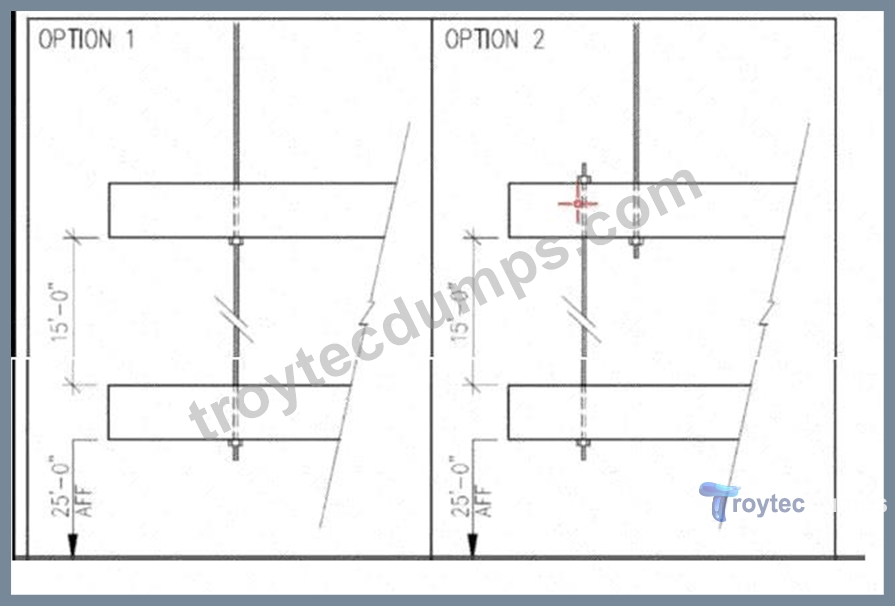
Answer:
Explanation: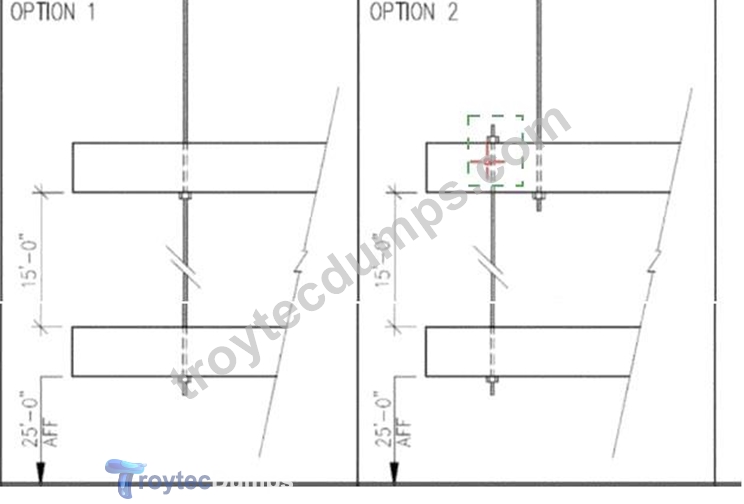
Explanation:
The upper nut at the top connection in Option 2 (the nut above the upper tube beam, highlighted at left).
By moving the threaded rod off the member's centroid in Option 2, the connection becomes eccentric. That eccentricity introduces a prying/bending moment at the rod/beam interface in addition to the vertical load from the banner and beam. In a through#rod with a nut above and below the member, the bottom nut primarily resists the direct gravity load in the concentric case (Option 1). When eccentricity is added (Option
2), rotation of the member about the rod induces additional uplift on the top nut (prying action), thereby increasing the force in the top nut relative to the concentric case.
Hence, the nut that will realize the greater load due to the proposed change is the upper nut at the top connection.
References
* NCARB ARE 5.0 PDD Handbook - Structural Systems & Detailing: Connections and eccentric loading.
* AISC Steel Design Guide: Prying Action in Bolted Connections (eccentric connections increase tensile force on the "prying" fastener).
* Ching, Building Construction Illustrated - Steel connections and load paths.
NEW QUESTION # 27
An architect is designing a sub-surface drainage system that outfalls into a site retention pond. The recommended shape, size, and slope of the drainage lines need to be determined for primarily which of the following purposes?
- A. To obtain the desired velocity
- B. To maximize the desired flow
- C. To increase the desired velocity
- D. To minimize the desired flow
Answer: A
Explanation:
In subsurface drainage system design:
The shape, size, and slope of drainage lines are selected primarily to achieve a desired flow velocity that prevents sedimentation and clogging but does not cause erosion.
Minimizing or maximizing flow is not the goal; the system must convey the design flow efficiently.
Velocity must be balanced - too low leads to sediment build-up; too high causes pipe damage.
Reference:
NCARB ARE 5.0 Review Manual, Site Design and Civil Engineering chapter
Drainage design principles from civil engineering manuals and EPA stormwater guidelines
NEW QUESTION # 28
In which of the following locations in concrete masonry should a control joint be placed?
- A. At the first course of masonry walls
- B. In the center of window openings
- C. At each corner of the foundation wall
- D. At changes in wall height
Answer: D
Explanation:
Control joints in concrete masonry walls are designed to accommodate movement caused by thermal expansion, moisture changes, and settlement.
Control joints should be placed at locations of stress concentration, such as changes in wall height, changes in wall thickness, or at large wall expanses.
They are not placed at the first course of masonry (which is typically reinforced and anchored to the foundation).
They are generally not placed at window corners or in the center of window openings but rather at planned intervals or changes in geometry.
Placing a control joint at changes in wall height allows movement without cracking.
References:
NCARB ARE 5.0 Review Manual, Materials and Assemblies chapter
Masonry design and control joint placement per ASTM standards
Masonry construction manuals (e.g., NCMA TEK)
NEW QUESTION # 29
Specifications and details for repointing deteriorated masonry joints in historic soft-brick buildings should result in which one of the following?
- A. The duplication of original mortar strength
- B. A bond between the existing masonry and the new mortar that is stronger than the brick
- C. Deeper joint profiles
- D. An increased mortar strength over the original mortar
Answer: A
Explanation:
Understanding the Problem
This question is about historic masonry restoration - specifically, repointing deteriorated mortar joints in soft-brick buildings.
Historic bricks, especially those made before the early 20th century, are often much softer and more porous than modern high-fired bricks. The mortar originally used was also softer, usually lime-based, which allowed for thermal movement, moisture permeability, and protection of the brick units.
Why the Correct Answer is "Duplication of Original Mortar Strength"
* Best practice in preservation (as outlined in the Secretary of the Interior's Standards for the Treatment of Historic Properties) is to match the original mortar in strength, composition, permeability, and appearance.
* A mortar stronger than the original can cause the softer brick to crack or spall under thermal or moisture stresses, because the brick will end up being the weaker link and take the damage.
* Duplication ensures that the new mortar works compatibly with the old masonry system - allowing for similar vapor transmission and structural flexibility.
Why the Other Options Are Incorrect:
* B. Increased mortar strength over the original mortar - This is harmful in historic soft-brick construction. Stronger cement-based mortars can trap moisture in the brick, leading to freeze-thaw damage and spalling.
* C. A bond stronger than the brick - This would cause the brick to fail first when stress occurs, which is undesirable in preservation work.
* D. Deeper joint profiles - Deeply raking out joints unnecessarily can damage surrounding brick edges and change the visual proportions; repointing depth should only be enough to remove deteriorated mortar (typically 2-2.5 times the joint width).
NCARB ARE 5.0 PDD Study Guide References:
* Content Area: Integration of Building Materials & Systems - Historic Preservation Techniques
* Key Resources:
* The Secretary of the Interior's Standards for Rehabilitation & Illustrated Guidelines for Rehabilitating Historic Buildings
* National Park Service Preservation Brief 2: "Repointing Mortar Joints in Historic Masonry Buildings"
* Building Construction Illustrated - Masonry Restoration
* Key Preservation Principle: "New mortar should match the historic mortar in composition, strength, and vapor permeability."
NEW QUESTION # 30
Which of the following metals is best suited for embedments in concrete or masonry?
- A. Aluminum
- B. Stainless steel
- C. Bronze
- D. Cast iron
Answer: B
Explanation:
When metals are embedded in concrete or masonry, corrosion resistance is a critical factor due to the alkaline environment and potential moisture exposure.
Stainless steel has excellent corrosion resistance, making it ideal for embedments in concrete or masonry where long-term durability is required.
Bronze is corrosion-resistant but typically used for decorative or hardware applications, not structural embedments.
Aluminum corrodes readily in alkaline concrete environments and is not suitable for embedments without protective coatings.
Cast iron is susceptible to rust and corrosion in moist conditions and is generally avoided for embedded components.
Thus, stainless steel is best suited for durability and corrosion resistance in concrete/masonry embedments.
References:
NCARB ARE 5.0 Review Manual, Materials and Assemblies chapter
Building construction materials standards (ACI, ASTM) on metals in concrete Corrosion resistance guides for metals embedded in concrete
NEW QUESTION # 31 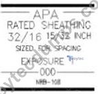
Refer to the exhibit.
For a plywood panel carrying the grade stamp shown, which of the following is the maximum recommended span for use in a floor system?
- A. 32 in
- B. 16 in
- C. 108 in
- D. 15 in
Answer: B
Explanation:
1. Understanding the APA Grade Stamp
The stamp in the exhibit reads:
* APA RATED SHEATHING 32/16
* 15/32 INCH (thickness)
* SIZED FOR SPACING
* EXPOSURE 1 (can handle temporary moisture exposure)
2. Meaning of "32/16"
The numbers 32/16 are the span ratings for the panel:
* 32 inches = maximum recommended span for roof sheathing (when applied perpendicular to supports).
* 16 inches = maximum recommended span for floor sheathing (when applied perpendicular to supports).
These ratings are established by APA (The Engineered Wood Association) based on panel thickness, grade, and allowable loads/deflection limits.
3. Applying to the Question
The question asks specifically for maximum recommended span for use in a floor system.
From the stamp:
* Floor span rating = 16 inches
* Therefore, the correct answer is 16 in.
4. Why Other Options Are Incorrect:
* A. 15 in - Not the value given; 16 in is the rating.
* C. 32 in - This is for roof applications, not floor systems.
* D. 108 in - Not related to APA span ratings; possibly confused with the certification number "NBR-
108."
5. NCARB ARE 5.0 PDD Study Guide References:
* Content Area: Building Materials & Assemblies - Wood Products
* Reference Sources:
* APA - The Engineered Wood Association: Panel Span Ratings Guide
* Building Construction Illustrated (Ching) - Plywood and OSB Panel Markings
* IBC Chapter 23 - Wood span and application requirements
NEW QUESTION # 32 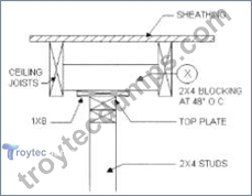
Refer to the exhibit.
What is the primary function of the 2 x 4 blocking shown at X in the drawing?
- A. Support the top of the partition
- B. Transfer the lateral load to the 1 x 8
- C. Transfer the lateral loads from the ceiling joists
- D. Brace the ceiling joists
Answer: D
Explanation:
Comprehensive Detailed Explanation with all NCARB ARE 5.0 Project Development and Documentation (PDD) Study Guide References:
In wood frame construction, blocking installed between joists at regular intervals (commonly 48 inches on center) serves primarily to brace and stabilize the joists laterally, preventing twisting and lateral displacement under load.
The 2x4 blocking at point X, placed perpendicular between the ceiling joists, acts as cross bracing.
It resists lateral torsional buckling of the joists and distributes loads evenly.
It also helps maintain alignment during construction and after the finish materials are installed.
The blocking does not support the partition top plate directly (that is the function of the studs beneath), nor does it transfer lateral load to the 1x8. Its main role is structural bracing for the joists.
Supporting References:
NCARB ARE 5.0 Review Manual, Project Development and Documentation, Structural Systems chapter Wood Frame Construction details from International Residential Code (IRC) Building construction texts such as "Fundamentals of Building Construction" by Allen and Iano, which describe blocking used to brace joists.
NEW QUESTION # 33
Where is the proper place to put a vapor barrier in a cold climate?
- A. On the interior between the gypsum wallboard and the framing
- B. On the exterior between the framing and the sheathing
- C. In the cavity of the framing space
- D. On the exterior between the metal siding and the sheathing
Answer: A
Explanation:
In cold climates, the vapor drive is from the warm interior to the cold exterior during winter. The vapor retarder/barrier belongs on the warm-in-winter side of the assembly-i.e., behind the interior gypsum, before the framing/insulation-to prevent interior moisture from reaching cold layers where it could condense.
PDD references: Psychrometrics & vapor drive; vapor retarder placement (ASHRAE; IBC/IECC guidance; ARE 5.0 PDD-Thermal & Moisture Protection).
NEW QUESTION # 34 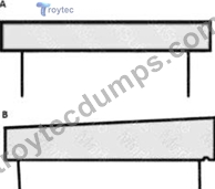
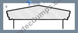
An architect is designing a school building that features a flat roof with a low parapet wall in a wet climate region. The client wants to minimize maintenance requirements and focus on keeping water from the walls.
What parapet coping detail would be most appropriate for the architect to select for this project?
- A. B
- B. A
- C. C
Answer: C
Explanation:
Understanding the Problem
The question addresses parapet coping design in a wet climate with a focus on:
* Minimizing maintenance
* Preventing water from running down the face of the wall
Parapet copings protect the top of the parapet wall from water penetration and are designed to shed water away from the wall below.
Analysis of the Options
A). Flat Coping
* A flat coping (Option A) has no slope and allows water to pool on the surface.
* This pooling increases the likelihood of infiltration and material deterioration over time.
* In wet climates, this is poor practice because standing water leads to freeze-thaw damage, staining, and faster degradation.
* Maintenance needs are higher.
B). Single-Slope Coping
* This coping (Option B) has a slope toward one side, which improves drainage.
* However, if sloped toward the inside of the parapet, it increases roof drainage load and risk of water penetration at roof/wall junction.
* If sloped toward the outside, water can run down the wall face, which the client specifically wants to avoid.
* This design might also stain exterior wall finishes over time.
C). Double-Slope (Pitched) Coping with Drip Edges
* This coping (Option C) is pitched toward both sides, with drip edges to break water runoff before it reaches the wall face.
* Water is shed away efficiently, and drip grooves prevent capillary action that would pull water back toward the wall.
* This is best practice in wet climates and greatly reduces maintenance by preventing staining and wall saturation.
* Recommended by NRCA (National Roofing Contractors Association) and referenced in Architectural Graphic Standards for parapet detailing.
NCARB ARE 5.0 PDD Reference:
* Content Area: Integration of Building Materials & Systems - Building Envelope Detailing
* Source Materials:
* Architectural Graphic Standards - Parapet Cap/Coping Details
* Building Construction Illustrated by Francis D.K. Ching - Water Management & Flashing
* NRCA Roofing Manual - Best Practices for Roof Edge & Parapet Design
* Key Principle: Parapet copings in wet climates should always slope to shed water away, incorporate overhangs with drips, and prevent water from cascading down the building face.
NEW QUESTION # 35
For the same moment, a glue-laminated beam would require a section modulus of what proportion relative to a sawn timber beam? (Assume F# of the glue-laminated beam is 2,400 psi and F# of the sawn lumber beam equals 1,200 psi.)
- A. 3/4
- B. 0
- C. The same
- D. 1/2
Answer: D
Explanation:
Comprehensive Detailed Explanation with all NCARB ARE 5.0 Project Development and Documentation (PDD) Study Guide References:
The question is about the relative section modulus (S) required for a glue-laminated beam vs. a sawn timber beam to resist the same bending moment. The formula relating bending stress (Fb), moment (M), and section modulus (S) is: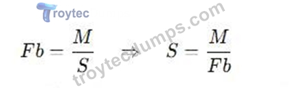
For the same bending moment M, the section modulus is inversely proportional to the allowable bending stress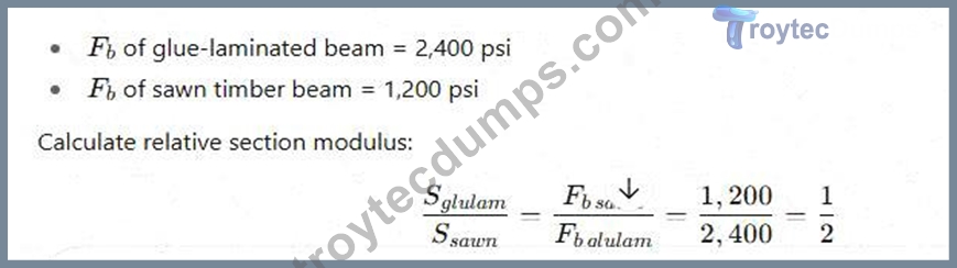
Therefore, the glue-laminated beam requires half the section modulus compared to the sawn timber beam.
Supporting Reference:
NCARB ARE 5.0 Review Manual, Structural Systems chapter
Basic bending stress and beam design equations from structural design texts
NEW QUESTION # 36 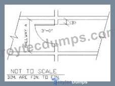
Refer to the exhibit.
Which of the following is the minimum dimension of Hallway A required to meet ADA requirements, if dimension (B) is 4 inches?
- A. 5 ft 0 in
- B. 4 ft 4 in
- C. 4 ft 10 in
- D. 3 ft 8 in
Answer: D
Explanation:
This question relates to ADA (Americans with Disabilities Act) minimum clear width requirements for hallways or corridors when doors swing into the corridor, affecting the clear width.
ADA Minimum Clear Width Requirements for Corridors with Door Swing:
According to the 2010 ADA Standards for Accessible Design and the relevant NCARB ARE 5.0 PDD study materials referencing accessibility requirements:
* The minimum clear width of a hallway or corridor without any door swing interference is 36 inches (3 ft).
* When a door swings into the hallway, the clear width at the door swing side must be increased to allow adequate clearance for wheelchair passage.
* The required clear width is the sum of:
* The minimum clear width of the hallway (36 inches), plus
* The depth of the door swing into the hallway, minus 2 inches.
Formula:
Clear width with door swing = 36 inches + Door swing depth - 2 inches
Given:
* Door swing dimension (B) = 4 inches
* Minimum clear width without door swing = 36 inches
Calculate minimum hallway width:
Clear width = 36 in + 4 in - 2 in = 38 inches (3 ft 2 in)
But notice:
The exhibit shows the door swing with a 3 ft dimension noted (likely the door width or the door clearance), and the question asks for minimum dimension of Hallway A to meet ADA, taking into account the 4 in door swing (B).
According to NCARB ARE 5.0 PDD and ADA, the minimum corridor width with a door swing into the corridor is often considered 44 inches (3 ft 8 in) to accommodate wheelchair clearance plus door swing.
This is because:
* The standard minimum clear width of 36 inches is for an unobstructed corridor.
* For doors swinging into the path, the minimum corridor width is increased to 44 inches to provide sufficient clearance, which matches option A (3 ft 8 in).
Supporting Reference:
* NCARB ARE 5.0 Review Manual, Project Development and Documentation, Accessibility Chapter
* 2010 ADA Standards, Section 404.2.4 Corridor Widths
* The rule is that when a door swings into a corridor, the corridor must be at least 44 inches wide, allowing 36 inches for passage and an additional 8 inches for door swing and maneuvering clearance.
Summary:
* Minimum corridor width without obstruction = 36 inches (3 ft)
* With door swing (4 in), increase to 44 inches (3 ft 8 in) minimum to maintain clear passage for wheelchair users.
NEW QUESTION # 37
Which of the following methods of mortar joint finishing has the greatest weatherability?
- A. Raked
- B. Concave
- C. Extruded
- D. Weathered
Answer: B
Explanation:
Mortar joint finishes impact water resistance and weatherability:
Concave joint is the most weather-resistant. The joint is compressed and curved inward, forming a dense, compact surface that sheds water effectively.
Weathered joint slopes outward but is less compact than concave.
Raked joint is recessed and can hold water, less weather-resistant.
Extruded joint protrudes and tends to trap water and dirt.
Therefore, concave joints provide the best weather protection.
Reference:
NCARB ARE 5.0 Review Manual, Materials and Assemblies chapter
Masonry construction standards and detailing guides
NEW QUESTION # 38
Temporary shoring of a masonry wall should remain in place until what point?
- A. Foundations are backfilled
- B. Lateral bracing connections are complete
- C. Horizontal reinforcing is installed
- D. Mortar joints are struck
Answer: B
Explanation:
(PDD) Study Guide References:
Temporary shoring in masonry construction supports walls until they gain sufficient stability. It should remain in place until:
The wall is laterally braced or tied back to a stable structure to resist wind and other lateral loads.
Mortar may have hardened but shoring removal depends on the overall stability.
Horizontal reinforcing and backfilling provide some support but do not replace lateral bracing.
Thus, temporary shoring should remain until all lateral bracing connections are complete, ensuring the wall's stability.
Reference:
NCARB ARE 5.0 Review Manual, Construction Methods chapter
Masonry construction standards and OSHA guidelines on temporary shoring
NEW QUESTION # 39 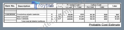
Refer to the exhibit.
Construction document drawings are in the final review stages. The architect needs to coordinate the casework detail with the probable cost estimate.
Click on the drawing note in the casework section that does not align with the cost estimate.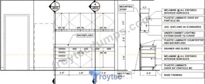
Answer:
Explanation: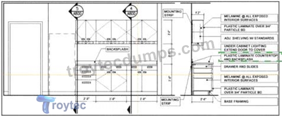
Explanation:
In the casework section drawing provided, the detail that likely does not align with the cost estimate is the note:
"PLASTIC LAMINATE COUNTERTOP AND BACKSPLASH"
This is often a higher-cost item compared to alternatives like post-formed countertops, solid surface over MDF, or budget composite finishes. If the project is under cost pressure, specifying both a plastic laminate countertop and a separate laminate backsplash can increase material and labor costs due to custom fabrication and edge treatments.
NEW QUESTION # 40 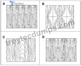
Refer to the exhibit.
Which of the following examples of wood paneling depicts the method of "slip matching" between adjacent wood veneers?
- A. B
- B. D
- C. C
- D. A
Answer: D
Explanation:
Understanding Slip Matching in Wood Veneer
When wood veneer is sliced from a log, each sheet (or "leaf") has a repeating grain pattern. How those sheets are arranged side-by-side on a panel is called the matching method.
Slip Matching:
* Consecutive leaves are laid side-by-side without flipping or reversing them.
* This creates a repeating grain pattern that flows consistently across the panel.
* The result is a uniform, continuous grain with no "mirror image" effect - the cathedrals and figure in the grain run in the same direction from sheet to sheet.
* Slip matching often produces a striped effect if the grain is straight, or a flowing, consistent repeat if the grain is more figured.
Identifying Slip Matching in the Exhibit:
* Option A shows consecutive veneer leaves with the grain pattern running in the same orientation across the panel - no mirroring, only repetition. This is classic slip match.
* Option B shows book matching - where every other leaf is flipped horizontally to create a mirrored grain pattern.
* Option C appears to be random matching - leaves are placed without grain sequence alignment.
* Option D shows reverse slip matching - similar to slip match but alternating leaves are reversed end- to-end.
NCARB ARE 5.0 PDD Study Guide References:
* Content Area: Integration of Materials & Finishes - Millwork and Casework Veneer Matching Methods
* Sources:
* Architectural Woodwork Standards (AWS) - Section on Veneer Matching
* Architectural Graphic Standards - Finish Carpentry and Veneer Matching
* Building Construction Illustrated (Ching) - Interior Finish Carpentry Key Point:
Slip matching keeps all veneer leaves in the same orientation, producing a consistent flow of the grain without the mirrored effect seen in book matching.
NEW QUESTION # 41
A family-owned apple farm in the Upper Midwest is taking advantage of a change in the local zoning code that added a new Agri-Tourism class in the existing farm zone. This allows the Owner to build a new facility on their existing site. The building will be open to the public and include a brewery, distillery, tap room, and market. The architect is ready to submit the drawings to the Owner for the 50% construction documents review.
To accommodate a compressed construction schedule, the Owner will be utilizing a design-build process. The Contractor has submitted the Pre-Engineered Metal Building (PEMB) shop drawings to the Architect for review, due to the lead time on this critical path item. Once construction begins, farming operations must be able to continue uninterrupted.
Key project information includes:
* Brewing and distilling will operate year-round.
* Brewery will initially include four fermenting tanks. Owner has requested space for at least two additional tanks. Potential expansion will be based on future sales.
* Distillery will produce 16% alcohol, which is classified as a flammable liquid. Fire separations are required.
* Tap Room is designed with seating for 300 people, not including exterior patio seating. It will have views to the working orchards and the historic buildings on site.
* Tap Room is scheduled to be open from August through November. Owner would like options to extend operating dates based on popularity.
* The Market area will feature local farm products and is not conditioned.
* Entire building will be fully sprinklered.
* Selected building materials are low-maintenance, as requested by the Owner, for durability and to reflect the nature of a working farm.
* Mechanical and electrical systems will be hung from the building structure. These loads are included in PEMB shop drawings.
* Public water and sewer is not available at the Project Site.
* Occupancy sensors are included to reduce utility costs and achieve energy conservation requirements.
The following resources are available for your reference:
* Architectural Drawings, including plans, elevations, sections, and schedules
* Consultant Drawings, including structural, HVAC, power distribution, and plumbing
* PEMB Shop Drawings
* Design and Construction Schedule
* Specification Excerpts, showing relevant spec sections
* IBC and ADA Excerpts, showing relevant code and accessibility sections
* After reviewing the documents, the architect discovers a coordination issue in the corridor.
The owner decides to triple the size of the distillery component of the project to make hand sanitizer and wants to use the Tap Room spaces adjacent to the brewery and distillery for this purpose.
Which of the following must the architect reevaluate and change to accommodate this request? Check the three that apply.
- A. A-04 REFLECTED CEILING PLAN
- B. A-05 ROOF PLAN
- C. A-06 EXTERIOR ELEVATIONS
- D. A-02 SITE PLAN
- E. A-03 FLOOR PLAN
- F. A-01 LIFE SAFETY PLAN
Answer: A,E,F
Explanation:
Tripling the distillery and converting adjacent Tap Room areas to production introduces additional hazard (flammable liquids), changes occupancies/occupant loads, and requires updated fire separations and egress.
A-01 Life Safety Plan must be revised for occupancy classification, fire#resistance ratings between uses, travel distances, exit widths/number, and signage.
A-03 Floor Plan must change to show new room uses, rated partitions/doors, openings, and equipment footprints.
A-04 Reflected Ceiling Plan must change for new/relocated rated assemblies at ceilings (e.g., continuity of fire
/smoke barriers), sprinkler/exit sign/FA device locations, and any duct-damper/access changes.
Site (B), Roof (E), and Elevations (F) are not directly driven by the interior use change.
PDD refs: IBC Chs. 3, 5-10 (occupancy, separation, egress), coordination of architectural, fire protection, and MEP on drawings (Division 01).
NEW QUESTION # 42 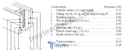
Refer to the exhibit.
What will the overall coefficient of Heat Transmission (U-value) of the building assembly illustrated in the attached figure become if unfaced R-19 batt insulation is added in the stud spaces in the wall cavity?
- A. 0.052
- B. 0.024
- C. 0.043
- D. 0.240
Answer: C
Explanation:
From the exhibit, the existing wall has a total thermal resistance R = 4.12.
Overall heat transmission (U-value) is U = 1/R = 1/4.12 # 0.24, which matches the figure.
If unfaced R#19 batt insulation is added in the stud cavity, the total resistance increases by 19:
A math equations and numbers AI-generated content may be incorrect.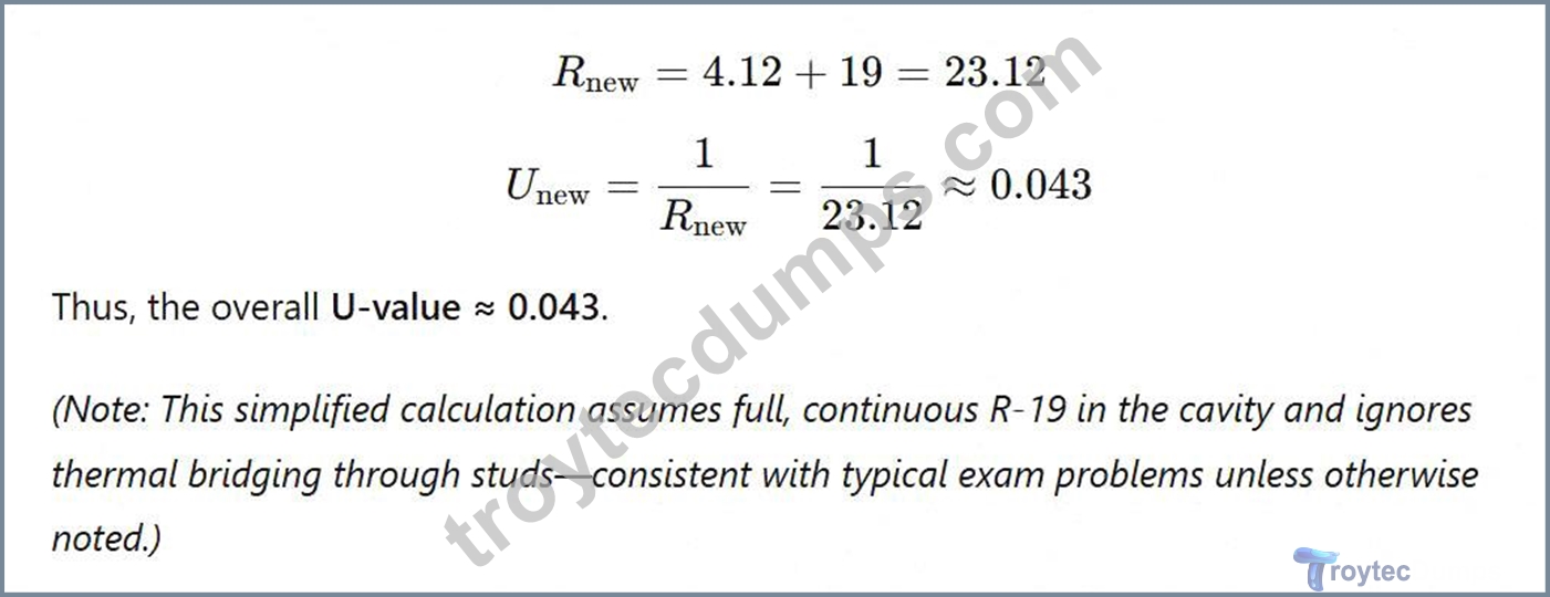
References (ARE PDD Study):
* Architectural Graphic Standards-Thermal properties of envelope assemblies; R and U relationships.
* Building Construction Illustrated (Ching)-Heat flow through walls and calculating U-values.
* NCARB ARE 5.0 Handbook-PDD: Building Envelope performance and energy calculations.
NEW QUESTION # 43
......
PDD Study Guide Realistic Verified Dumps: https://www.troytecdumps.com/PDD-troytec-exam-dumps.html
Accurate PDD Questions with Free and Fast Updates: https://drive.google.com/open?id=1Y2Ik8N_lTWv3io78S9B3S4NIgCVqHO73